
At 7:30 a.m., a mine maintenance site in Western Australia got ready for inspection tasks of the day. The steel plate transition zone at the workshop entrance was covered with a thin layer of red soil dust. Spare hoses, maintenance tool trolleys and disassembled pump parts were placed nearby.
The equipment to be moved that day was a 42-ton slurry pump skid module. It needed to be transferred from the maintenance bay to the adjacent assembly area over a distance of around 35 meters. No long-distance transport or heavy lifting was required. However, the moving route included concrete flooring, steel plate transition sections, partially compacted red soil ground, plus a turning point of roughly 45 degrees.
The challenge for the on-site maintenance team was not “whether the load can be moved”. Instead, they needed to keep the equipment stable within narrow aisles and reduce repeated close-range pushing, pulling, shimming, and direction correction by workers.
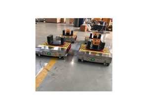
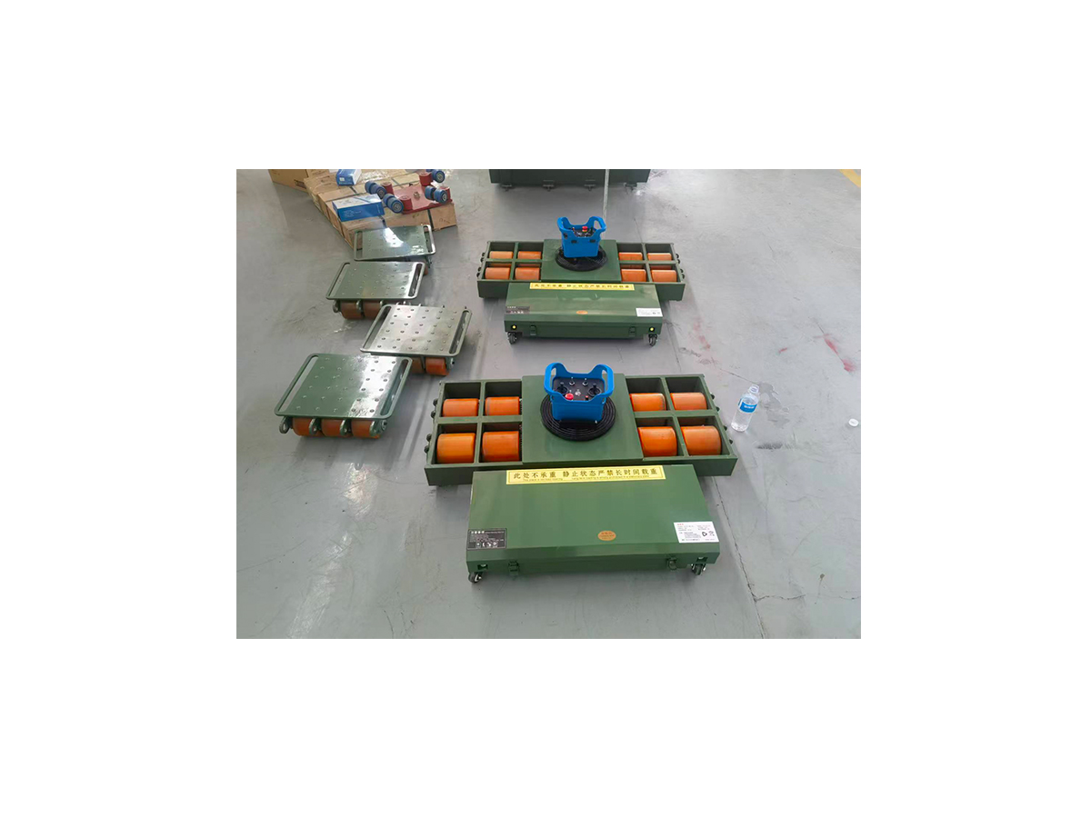
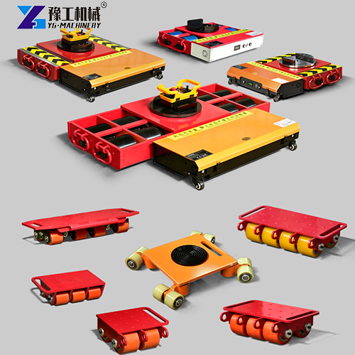
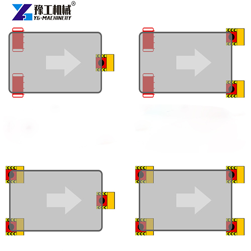
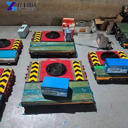
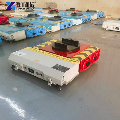
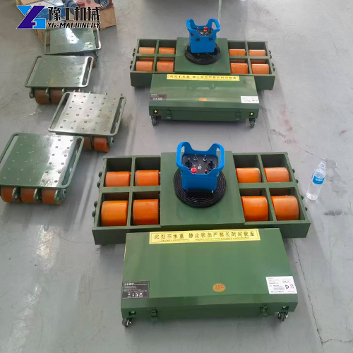
The project finally adopted a four-point support heavy-duty moving system made up of 2 powered master units plus 2 slave load modules, namely electric machinery moving rollers. After wireless pairing of the two master units, one operator controlled travel direction, speed, steering, and stop uniformly via a single industrial remote controller. The two slave wheels bore corresponding loads and moved together with the whole equipment. A second on-site staff member monitored wheel sets, aisle clearance, ground conditions, and equipment posture.
Electric Machinery Moving Roller Specifications
| Model | 10T | 20T | 25T | 30T | 40T | 50T | 60T |
| Motor | 500W ×2Brake 104Flange reinforced gearbox | 750W ×2Brake 104Flange reinforced gearbox | 1000W ×2Brake 104Flange reinforced gearbox | 1200W×2 Brake 120 Flange reinforced gearbox | 1500W ×2Brake 120Flange reinforced gearbox | 2000W ×2Brake 120Flange reinforced gearbox | 3000W ×2Brake 120Flange reinforced gearbox |
| Controller | D2T80ADual-channel driver | D2T80ADual-channel driver | D2T100ADual-channel driver | D2T100ADual-channel driver | D2T200ADual-channel driver | D2T200ADual-channel driver | D2T220ADual-channel driver |
| Remote Controller | C7 remote controller | C6/C7 remote controller or industrial remote controller | C7 remote controller | C7 remote controller | C6/C7 remote controller or industrial remote controller | C7 remote controller or industrial remote controller | C7 remote controller or industrial remote controller |
| Battery Spec | 48v 30Ah ternary lithium | 48V 60Ah ternary lithium or LFP | 48V 60Ah ternary lithium or LFP | 48V 60Ah ternary lithium or LFP | 48V 120Ah ternary lithium or LFP | 48V 120Ah ternary lithium or LFP | 48V 120 Ah ternary lithium |
| Working Current | 25A | 60A | 60A | 60A | 120A | 120A | 120A |
| Charging Current | 54.6 | 54.6 | 54.6 | 54.6 | 54.6 | 54.6 | 54.6 |
| Drive Wheel | 80*120×4High-hardness fully imported polyurethane | 90×135×4High-hardness fully imported polyurethane | 90×135×4High-hardness fully imported polyurethane | 90×135×4High-hardness fully imported polyurethane | 140×140×4High-hardness fully imported polyurethane | 140×140×4High-hardness fully imported polyurethane | 140×140×8High-hardness fully imported polyurethane |
| Gear | Luomengtai high-strength gear3-module | Luomengtai high-strength gear3-module | Luomengtai high-strength gear3-module | Luomengtai high-strength gear3-module | Luomengtai high-strength gear3-module | Luomengtai high-strength gear3-module | Luomengtai high-strength gear3-module |
| Plate Material | 10mmQ355 manganese steel plate | 10mmQ355 manganese steel plate | 12mmQ355 manganese steel plate | 12mmQ355 manganese steel plate | 16mmQ355 manganese steel plate | 16mmQ355 manganese steel plate | 16mmQ355 manganese steel plate |
| Traction Weight | 10T | 20T | 25T | 30T | 40T | 50T | 60T |
| Load Capacity | 10T | 10T | 12.5T | 15T | 20T | 25T | 30T |
| Overall Dimension | 500x550x145mm | 670x620x165mm | 670x635x165mm | 740x640x185mm | 810x800x182mm | 810x800x182mm | 1110x800x185mm |
| Disc Flange | 2900MM diameter | 2900MM diameter | 2900MM diameter | 2900MM diameter | 2900MM diameter | 2900MM diameter | 2900MM diameter |
| Travel Speed | 2-10 m/min adjustable | 2-10 m/min adjustable | 2-10 m/min adjustable | 2-10 m/min adjustable | 2-10 m/min adjustable | 2-10 m/min adjustable | 2-10 m/min adjustable |
| Continuous Working Time | 2-3 hours | 3-4 hours | 3-4 hours | 3-4 hours | 4-5 hours | 4-5 hours | 4-5 hours |
A Common Mine Maintenance Task
Short-distance relocation inside mine maintenance areas may not draw as much attention as heavy lifting projects, yet it often impacts maintenance schedules and equipment availability.
This pump skid module had to be moved out of the maintenance bay on the same day so that the next waiting machine could be brought in. Any delay in relocation would push forward subsequent disassembly, inspection, spare part replacement, and reassembly. Meanwhile, the maintenance workshop had limited space. Forklifts, hydraulic jacks, tool trolleys, spare part racks, and workers all needed to coordinate within the same zone.
The client initially considered two common solutions.
The first option was large-tonnage forklifts paired with hydraulic jacks. Forklifts can provide traction. But after a site survey, the bottom structure of the pump skid was not suitable for direct support by fork tines. Once the forklift entered the maintenance bay, turning space was tight, and the driver had poor visibility beside and behind the equipment.
The second choice was hydraulic jacks plus traditional heavy equipment moving rollers. This method is widely used. However, the team expected multiple stops, lifting, roller repositioning, and manual direction correction at steel plate transition zones and turning points.
“The equipment itself is nothing special. The real issues are limited space and tight work schedule,” said the on-site maintenance coordinator. “If every direction adjustment requires multiple workers to push, pull, and correct close to the machine, work slows down, and personnel positions become harder to manage.”
Instead of simply picking one type of handling gear, the client re-evaluated which moving method would make the whole operation controllable under the given route and staffing constraints.
Electric Machinery Moving Roller Procurement Evaluation: Shift from Tonnage Comparison to Load & Control Logic
When assessing the electric solution, the procurement team did not only compare rated load capacity. They first confirmed the total pump skid weight, center of gravity, bottom structure, and available support points, and inspected the full route from maintenance bay to assembly zone.
The project team verified these key points:
- How to reasonably distribute the 42-ton pump skid load across four support points
- Whether wheel sets can travel safely over concrete floors, steel plate transitions, and compacted red soil
- Whether slight height differences at steel plate edges affect low-speed movement
- Whether the equipment can complete roughly 45° direction adjustment in narrow aisles
- Whether operators can maintain clear sightlines outside the moving path
- If two master units can pair wirelessly and respond synchronously to commands from one remote controller
- Whether battery power covers movement, fine adjustments, and reset tasks on the day
- How braking, emergency stop, remote control, and isolation procedures fit mine work permit requirements
Finally, the client evaluated and adopted the four-point support setup with 2 powered master units and 2 slave load modules.
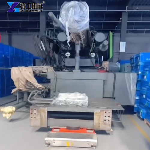
Two electric machinery moving rollers were installed below confirmed load points on the drive side to deliver travel, steering, and braking functions. The two slave wheels sat under the other two support points to bear corresponding loads and follow the overall movement of the pump skid.
This configuration was not designed to simply add up the rated tonnage of individual units. After verifying the pump skid’s center of gravity, support structure, and force on each load point, it delivers more stable multi-point support for such modules. Placement of master and slave units, load ratio, and moving direction still need confirmation based on equipment structure, floor conditions, and task risk assessment.
The power unit of battery powered machine moving skates adopts a 48V 120AH battery system. Under applicable load and ground conditions, its continuous working time is 4 to 5 hours. For this 35-meter low-speed phased relocation task, the client cared less about “running nonstop for a full day”. Their priority was sufficient battery reserve for start-stop cycles, steering adjustments, re-movement after inspection, and required return positioning.
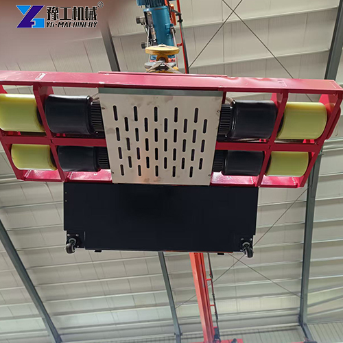
The system uses D2T200A dual-channel drivers, drive motors with braking function, and reinforced gearboxes. The platform is built with 16mm Q355 manganese steel plate. The transmission uses Luomengtai high-strength gears with a 3-module design. High-hardness polyurethane drive wheels maintain stable ground contact on cleaned and inspected floors.
These parameters are not a guarantee of zero failure in all mine environments. For buyers in remote mine sites, they represent structural and maintenance details to verify during equipment selection. In remote areas, repair resources, spare parts, and technical support are not as easily accessible as in urban industrial zones.
Another key reason for selecting this solution is wireless synchronization between the two master units. After wireless pairing, a single operator can send unified forward, backward, left turn, right turn, deceleration, and stop commands to both masters via one industrial remote controller.
The industrial remote controller has a rated effective control distance of up to 50 meters. For this 35-meter moving route, the operator could stand at a safe observation position in front of and to the side of the pump skid, watching ground status, steel plate transition zone, travel path, and final turning point at the same time.
Unified remote operation does not remove the need for on-site assistance. The operator issues all movement commands. The observer monitors wheel set status at four support points, clearance between equipment and surrounding obstacles, ground changes, and whether the pump skid keeps a stable posture.
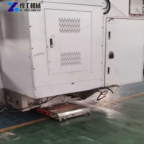
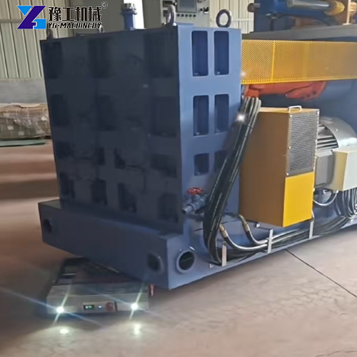
On-site Execution: Four-point Support Relocation with 2 Master Units & 2 Slave Wheels
07:30: Lifting, Placement & Route Clearing
Before formal operation, the maintenance team lifted the pump skid to the proper height for installing moving gear using hydraulic jacks.
Based on the equipment center of gravity and bottom load-bearing structure, the team laid out 2 powered master units and 2 slave load modules. Two master units were fitted under confirmed drive and steering load points; two slave wheels were placed under the remaining two support points.
After all modules were positioned, on-site staff checked the contact status of the four support points to rule out obvious unbalanced load, suspension, or abnormal local stress. The two master units completed wireless pairing, and the assigned operator controlled everything with one industrial remote controller. Slave wheels do not receive separate travel commands; they work as passive load-bearing units following the pump skid movement.
Then the team cleared loose dust, tools, and scattered materials from concrete floors, steel edges, and local red soil areas. Temporary isolation zones were set around the equipment. Unauthorized personnel were kept out of areas where the machine might shift or create pinch points.
Pre-job briefing defined these rules:
- Only the assigned remote operator may issue movement commands
- The observer checks wheel sets, equipment clearance, and travel route
- The machine runs at low speed, with planned stops at steel plate transitions and turning zones
- Stop immediately if wheel offset, abnormal ground surface, communication failure, or posture change appears
- Lifting, repositioning master/slave units and final support work can only be carried out after full equipment stop
08:15: Synchronized Control of Two Masters, Four-point Support Starts Moving
The pump skid began to leave its original maintenance bay.
Two electric machinery moving rollers finished wireless pairing and entered synchronous linkage. Instead of switching control separately for each master, the operator sent unified forward, backward, steering, deceleration, and stop commands via the same remote controller.
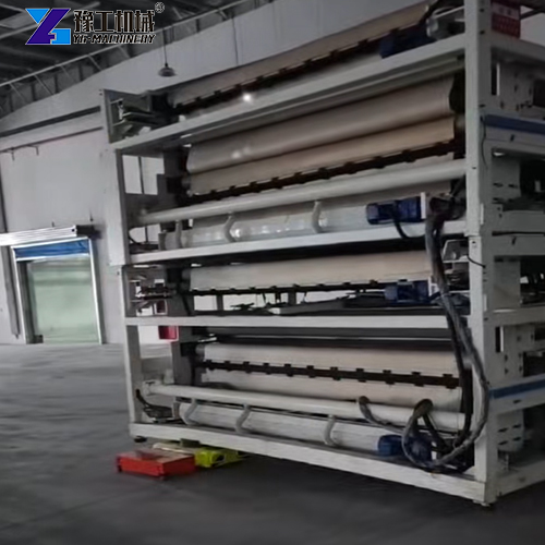
The two slave wheels provide no active driving force but support the pump skid at the other two load points and follow the overall moving path. In this way, the pump skid maintains four-point load bearing while driving, steering, and braking are handled centrally by the two master units.
The operator did not start continuous travel right away. Short low-speed test runs were carried out first to confirm both masters respond consistently to start, stop and steering orders. The observer stood at a safe side position to check whether slave wheels take load correctly, wheel sets run smoothly, and the pump skid moves along the planned route.
For the first 15 meters of straight travel, two scheduled stops were arranged:
- First stop: inspect contact condition of four support points and pump skid posture
- Second stop: confirm proper travel direction of master drive wheels and slave wheels as equipment approaches steel plate transition zone
The value of unified control became clear at this stage. Identical travel, stop, and steering commands sent to both masters reduce repeated correction caused by one unit starting earlier or lagging behind. Still, the team did not treat it as “auto-sync with no inspection needed”. The observer continued verifying actual movement at every step.
09:00: Low-speed Passage across Steel Plate Transition Zone
The steel plate transition zone at the workshop entrance required the most careful handling on that day.
There was no major slope, but a slight height difference existed between the concrete floor and steel plates, and red dust easily accumulated on steel surfaces. The team cleaned this area before work and guided the equipment toward the steel edge at low speed in a near-perpendicular direction.
Standing on the front-left side of the pump skid, the operator sent unified low-speed forward commands to the two battery powered load moving skates via remote controller. The observer stood sideways outside potential pinch zones and watched master and slave wheels pass the transition edge one by one.
High-hardness polyurethane drive wheels deliver controlled ground contact here. They cannot eliminate ground influences completely. When crossing steel edges, the team followed this rhythm: move a short distance → stop and inspect → continue after confirmation.
The whole crossing took roughly 12 minutes. On-site records showed no obvious wheel slip, pump skid shift, or change of slave wheel load position.
09:35: Synchronized 45° Turning by Two Master Units
After entering the adjacent assembly zone, the pump skid needed roughly 45° direction adjustment to align with the new maintenance bay.
For traditional heavy equipment moving rollers, this usually means lifting again, reorienting rollers, then manual pushing/pulling plus multiple corrections to finish turning. If multiple roller units move independently, minor speed differences on either side can pull the equipment off course.
On this project, the operator sent small steering and travel commands to both masters via one remote controller. Both master units responded under the same control logic, and slave wheels followed along the pump skid’s overall path.
The team avoided completing the whole turn in one single movement. The work was split into multiple small low-speed steps. After each angle adjustment, the machine stopped for the observer to check:
- Clearance between pump skid and racks, columns, tool trolleys and tooling
- Whether two master units and two slave wheels run along expected paths
- Stable load bearing at all four support points
- Whether steel edges and floor joints affect equipment posture
- Normal remote communication, brake response and operation commands
“When we used separate roller sets before, we often had to call a stop and get people at different spots to adjust separately,” the on-site maintenance coordinator said. “This time one operator controls forward, stop, and steering for both masters, and slave wheels carry load at the other two support points. Observers still have to be present, yet the whole movement and communication flow is much more streamlined.”
10:20: Preliminary Positioning & Subsequent Maintenance
At about 10:20 a.m., the pump skid reached preliminary positioning.
Once fully stationary, the maintenance team used hydraulic jacks for final support adjustment, then removed the two master units and two slave wheels from underneath the pump skid. Subsequent alignment, connection, trial run, and repair work followed standard mine procedures.
From lifting, route clearing, and placing 2 master +2 slave modules to preliminary positioning, the whole process took around 3 hours. This is not defined as an extreme efficiency breakthrough, but a reasonable result matching equipment weight, travel length, workspace, inspection checkpoints, and low-speed operation requirements.
Speak with Our Product Manager
Project Result: Reduce Repeated Adjustment, Not Full Replacement
After completion, the client carried out an internal review of this relocation method. The team did not treat this system as a universal replacement for all moving jobs, and clarified its applicable scenarios for short-distance transfer inside maintenance workshops.
Key recorded outcomes of this operation:
- 42-ton pump skid relocated 35 meters short distance using 2 powered master units +2 slave wheels four-point support configuration
- After wireless pairing, one single operator controlled forward, backward, steering, deceleration, and stop of two master units via one industrial remote controller
- Two slave wheels acted as passive bearing modules to carry corresponding load and move with the equipment at other support points
- Actual movement completed with one remote operator plus one observer
- Pump skid crossed steel plate transition zone and finished staged 45° direction adjustment in assembly area
- Compared with the originally planned manual roller scheme, repeated lifting, repositioning, and manual pushing during turning were reduced
- Post-job inspection found no obvious cosmetic equipment damage directly caused by relocation
- Battery retained usable reserve after finishing scheduled tasks for the day
Application Scope of Electric Machinery Moving Roller
Four-point support systems consisting of 2 master units +2 slave wheels are generally suitable for equipment with multiple defined bottom support points requiring stable short-distance movement, such as:
- Slurry pump skids, compressor modules and water treatment equipment bases
- Generator sets, power modules and large motor bases
- Transformer bases, power distribution modules and large electrical equipment
- Prefabricated steel structures, long tooling and heavy mold bases
- Large mechanical assemblies in port yards or construction sites
The core value of multi-unit unified control is not “auto-handling without human input”. After pairing, communication inspection, and proper setup, two master units receive unified movement commands under the same control logic.
This setup lowers risks of inconsistent movement when starting, stopping, or steering between two master units. However, it cannot automatically eliminate risks of unbalanced load, poor ground conditions, communication loss, or equipment posture shift. Slave wheels do not “automatically balance all loads”; they must bear pre-defined loads on verified support points.
For real projects, these checks are still mandatory:
- Whether the load capacity of master and slave units covers the actual distributed load
- Whether the pump skid or equipment bottom structure fits four-point support
- Whether two master units maintain proper drive and steering performance along the route
- Stability of slave wheels crossing floor joints, steel plates, thresholds and uneven ground
- Whether operators, observers, isolation zones and emergency stop procedures meet site requirements
Speak with Our Product Manager
Unified Control Does Not Replace On-site Judgement
This relocation project in a Western Australian mine maintenance area did not rely on ultra-heavy tonnage, long-distance haulage or complex lifting. It solved a common on-site challenge: moving a 42-ton pump skid stably and controllably over a short distance within narrow aisles, mixed ground surfaces, and tight maintenance windows.
The four-point support heavy-duty moving roller system, electric machinery moving roller, built with 2 powered master units and 2 slave wheels, provides centralized control for project teams. After wireless pairing of the two masters, one operator controls travel direction, speed, steering, and stop with a single remote controller. Slave wheels deliver passive bearing at other load points.
This configuration cannot replace lifting work, route preparation, ground inspection, safety isolation, observers, and risk assessment. For pump skids, generator modules, prefabricated steel structures, transformer bases, and other multi-support heavy loads, under suitable conditions, it reduces communication pressure from separately operating multiple powered units and cuts repeated repositioning and manual correction work.
If your project also needs to move heavy modules inside mine maintenance zones, port yards, or construction sites, when evaluating this type of electric heavy equipment moving roller, start from your actual task: What support points does the equipment have? How much load does each point take? What ground and transition zones lie along the route? Are 2 master units plus 2 slave wheels compatible with the equipment structure? Where will the operator stand? How can observers detect and handle abnormalities?
Answers to these questions usually decide whether heavy equipment relocation stays controllable, more than the rated tonnage marked on equipment nameplates.