
In modern geological exploration and mine Grade Control construction, Reverse Circulation (RC) drilling has become the preferred technology for shallow and medium-depth exploration, thanks to its fast sampling speed, high sample representativeness, and low contamination rate. However, RC drilling is essentially a systematic project powered and driven by high-pressure and large-volume compressed air. If the lifting capacity of RC drilling equipment fails to precisely match the air volume (CFM) and air pressure (Bar) of the air compressor, it will easily lead to bottom hole cuttings accumulation, drill jamming, reduced sample representativeness, and even equipment overload.
Based on the fluid mechanics requirements of reverse circulation drilling, this article systematically explains the matching logic between RC drilling equipment selection and high-pressure air compressor configuration.
Core Physical Logic of Air Compressor Matching
The air compressor undertakes two core tasks in RC drilling: driving the DTH Hammer to break rock and transporting rock cuttings back to the ground at high speed through the inner tube of drill rods.
High-pressure air flows downward through the annulus → drives the DTH Hammer for rock breaking → air blows at the borehole bottom → carries cuttings upward at high speed inside the inner tube to the ground
Two key parameters must be fully considered for compressor configuration:
Pressure (Bar/PSI): Determines maximum drilling depth and water resistance
- Overcome pressure loss of DTH Hammer and pipeline friction
- Counteract downhole hydrostatic pressure (every 100 meters of water head generates approximately 10 Bar backpressure when drilling into aquifers)
Flow Rate (CFM/m³/min): Determines cuttings removal efficiency and continuous sampling performance
- Maintain critical upward velocity of 20–30 m/s inside the inner tube for effective cuttings discharge
- Insufficient airflow causes cuttings to settle inside the inner tube, resulting in pipe blockage or secondary crushing of samples
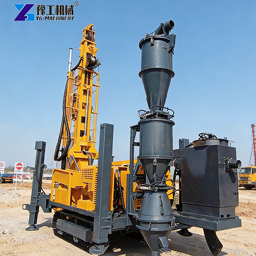
Matching Table for Drilling Depth, Hole Diameter and Air Compressor Parameters
According to engineering experience and fluid mechanics calculations, the recommended reverse drilling machine models and corresponding compressor parameters for different drilling depths and hole sizes are listed below:
| Exploration Depth (m) | Common Hole Diameter (inch/mm) | Drill Rig Rotary Torque (N·m) | Drill Rig Lifting Force (kN) | Recommended Compressor Pressure (Bar/PSI) | Recommended Compressor Flow (CFM/m³/min) | Typical Application Scenarios |
| 0 – 150 | 4.5″ (114mm) | 3,000 – 5,000 | 100 – 150 | 25 Bar (360 PSI) | 900 CFM (25.5 m³/min) | Open pit mine grade control, shallow general survey |
| 150 – 300 | 5.5″ (140mm) | 5,000 – 8,000 | 150 – 220 | 30 – 35 Bar (435–508 PSI) | 1,000 – 1,150 CFM (28.3–32.5 m³/min) | Standard mineral tenure exploration, medium-deep strata investigation |
| 300 – 500 | 5.5″ – 6″ (140–152mm) | 8,000 – 12,000 | 220 – 350 | 35 Bar + Booster (Up to 50 Bar) | 1,200 – 1,350 CFM (34–38 m³/min) | Deep ore body delineation, complex high water-bearing formations |
Note: When drilling depth exceeds 350 meters or working in water-rich formations, a single compressor cannot supply enough pressure. A series connection mode of “main air compressor + secondary high-pressure Booster” is generally adopted to lift pressure above 50 Bar and offset strong hydrostatic backpressure.
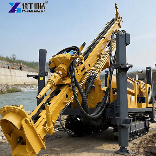
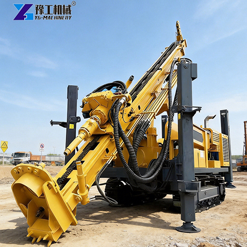
Three-Step Calculation Method for Reverse Circulation Drill Rig Selection & Matching
Three steps can be followed for accurate verification during on-site equipment selection:
Step 1: Inner tube air velocity check (calculate minimum airflow)
Calculate the minimum required airflow to reach critical cuttings lifting velocity based on inner tube cross-sectional area:
Qmin= Utarget × Ainner × 60 × Ccomp
Utarget: Target upward velocity inside inner tube, normally set at 25 m/s
Ainner: Cross-sectional area of dual-wall drill rod inner tube (m²)
Ccomp: Correction factor accounting for gas compression with increased drilling depth
Step 2: Downhole water pressure & pipeline loss calculation (calculate minimum pressure)
Ptotal= Phammer + Ploss + (ρw × g × Hw)
Phammer: Rated working pressure of DTH Hammer (normally 18-25 Bar)
Ploss: Pressure loss along pipelines and cyclone separator (reserve 3-5 Bar margin)
Hw: Predicted water head of aquifer (approximately 1 Bar extra pressure required per 10 meters of water depth)
Step 3: Matching between reverse circulation drill rig lifting force and drill string weight
The rated lifting force of the reverse circulation drill rig must be 1.5 to 2 times the total weight of drill tools at maximum drilling depth (safety factor), to provide sufficient pulling force in case of hole collapse, hole shrinkage, or sticking in wet clay layers:
Flift ≥1.5 × (Lmax × Wrod + Whammer)
Lmax: Maximum designed drilling depth (m)
Wrod: Weight per meter of dual-wall drill rod (kg/m; 4.5” rod weighs roughly 22-28 kg/m)
Whammer: Total weight of DTH Hammer and drill bit (kg)
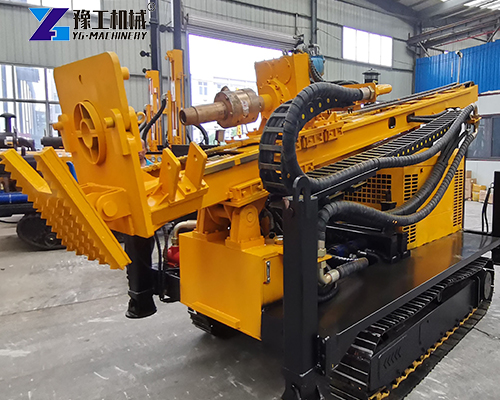
Common On-Site Matching Misunderstandings & Avoidance Guide
- Misconception: Higher airflow equals universal performance: Excessive airflow with insufficient pressure leads to gas bypass at dual-wall drill rod joints or air chambers, failing to overcome bottom hole backpressure. Meanwhile, velocity over 35 m/s inside the inner tube causes severe abrasion on inner pipes and elbows, shortening the service life of drilling tools.
- Ignoring power attenuation at high altitudes: When air compressors operate at elevations above 3000 meters, thin air reduces actual exhaust volume and engine output by 15%–25%. For high-altitude projects, specify compressors with 1.2–1.3 times nominal airflow as redundancy.
- Pressure reserve for wet drilling (water/foam injection): Dry cuttings discharge works well in dry formations, but rock powder easily clogs and sticks to inner tubes in slightly water-bearing strata. A small amount of water or foaming agent needs to be injected for wet flushing, which greatly increases the flow resistance of the gas-liquid mixture. Reserve at least 20% extra pressure for the air compressor in this case.
Conclusion
Selecting RC drilling equipment is never a simple purchase of standalone equipment, but a dynamic balance among three systems: drill rig lifting & torque system, compressor pressure & airflow system, and dual-wall drill string system. During procurement and project configuration, calculate pressure based on the maximum designed depth and predicted highest groundwater level, and calculate airflow according to the inner diameter of drill rods. Only in this way can an RC drill rig achieve high penetration rates and high-quality sampling with optimal overall performance in complex geological conditions.